TTEC 4826 – Engine Electronic Control Systems
Ignition timing
Ignition timing, in a spark ignition internal combustion engine, is the process of setting the time that a spark will occur in the combustion chamber (during the compression stroke) relative to piston position and crankshaft angular velocity.
Setting the correct ignition timing is crucial in the performance of an engine. The ignition timing affects many variables including engine longevity, fuel economy, and engine power. Modern engines that are controlled by an engine control unit use a computer to control the timing throughout the engine's RPM range. Older engines that use mechanical spark distributors rely on inertia (by using rotating weights and springs) and manifold vacuum in order to set the ignition timing throughout the engine's RPM range. There are many factors that influence ignition timing. These include which type of ignition system is used, engine speed and load, which components are used in the ignition system, and the settings of the ignition system components. Usually, any major engine changes or upgrades will require a change to the ignition timing settings of the engine.
Sensors
Note: the term TPS can mean either throttle position sensor or throttle position switch
Throttle Position Sensor (potentiometer)
A throttle position sensor (TPS) is usually located on the butterfly spindle so that it can directly monitor the position of the throttle valve butterfly.
The sensor provides a variable resistance dependent upon the position of the throttle position.

More advanced forms of the sensor are also used, for example an extra closed throttle position sensor (CTPS) may be employed to indicate that the throttle is completely closed.
Some ECUs also control the throttle position and if that is done the position sensor is utilised in a feedback loop to enable that control.
Related to the TPS are accelerator pedal sensors, which often include a wide open throttle (WOT) sensor. The accelerator pedal sensors are used in "drive by wire" systems, and the most common use of a wide open throttle sensor is for the kick down function on automatic transmissions.
Potentiometer type sensors are composed of variable resistors that have a slide contact, which changes its position as the throttle butterfly moves.
A voltage is supplied to the sensor by the E.C.U. As the throttle position changes, the output voltage from the sensor changes, this in turn is recognised and a comparison made by the E.C.U to its memory. These sensors are adjusted by loosening the sensor mounting screws. (It is critical that you follow the manufacturer’s set-up procedure)
For example:
The idle position is recognised by the lowest voltage reading through the sensor but in contrast, the maximum power signal is recognised by the highest reading at the full throttle position of the sensor travel. It is important that both signals are correct.
Checking the Throttle Position Sensor
Terminal connections;1234=ABDC
This is a Throttle Position Sensor (potentiometer) type of TPS.

Note that these TPS’s do not last forever, the carbon track wears out, and leaving dead spots were no reading will be given.
A potentiometer (POT) varies from a variable resistor/rheostat in that a POT has 3 connections and the variable resistor/rheostat has 2 and the third is not connected.
Now connect a Power Supply to your sensor and test the voltage output at different throttle angles.
NOTE: Always use a 5V supply
Table of Angle of degrees of advance Vs the output Voltage
Throttle angle degrees | Voltage output V |
0 | 1.07 |
10 | 2.01 |
20 | 2.5 |
45 | 3.45 |
70 | 3.6 |
88 | 3.8V |
Throttle Position Switch
There is an idle position signal that is used mainly for fuel cut-off control and ignition timing corrections. The power signal is created at full throttle and is used for increasing fuel injection volume which in turn increases engine power output. Note there is no switching at part throttle.
Throttle position switch detects throttle position at idle or full throttle by using switch contacts that are connected or disconnected as throttle position changes.
This type of switch can have two or three contact positions and is usually checked and adjusted using a multi-meter.
Adjustment is made by loosening the mounting screws and rotating the switch assembly.

Two position (three pin) or
Three position (four pin)Testing the throttle position switch
A faulty throttle position switch (TPS) can result in a number of poor running problems. Because they can result in such a large number of problems, faulty switches often go undiagnosed. The other thing that makes TPS problems difficult to diagnose is that they quite often only appear when the engine is warmed up (throttle position switch warmed up).
The following lists some of the symptoms that MAY indicate a problem with the throttle position switch:
Poor idle - particularly a high idle condition
Engine cuts out to an idle condition during acceleration
Poor power at various RPMs (various throttle positions)
Surging idle
Misfire
Stumble during acceleration
Intermittent boost problems (turbocharged cars)
Note: PSW means power switch (WOT)
IDL means idle circuit
E means earth
Resistance Testing the Throttle Valve Opening showed that there was continuality (0.03 ohms) between EDL and E at 0 degrees and at wide open there was no continuality (OL).
Resistance testing on PSW and E gave the opposite readings; OL when closed and 0.02 when the throttle is wide open.
Manifold Absolute Pressure (MAP) provides instantaneous manifold pressure information to the engine's electronic control unit (ECU). The data is used to calculate air density and determine the engine's air mass flow rate, which in turn determines the required fuel metering for optimum combustion. A fuel-injected engine may alternately use a MAF (mass air flow, see below) to detect the intake airflow. A typical configuration employs one or the other, but seldom both. It is important to understand the effects of engine condition/load or throttle opening has on the pressure within the inlet-manifold. At idle when the throttle is closed a high vacuum or negative pressure is produced. As the engine is still sucking but the air flow is restricted by the throttle butterfly. When the throttle is opened the pressure inside the manifold rises, how quickly the throttle butterfly is opened affects the speed of this change. It can be seen that poor engine condition or air leaks in the induction manifold will lead to poor engine performance and erratic idling. Typical idle condition resulting from an air leak is hunting, this is when at idle the engine RPM rises and lowers in a regular pattern.
Wire up a map (manifold absolute pressure) sensor with a 5 V feed and earth. Measure the return voltage from the third wire.
Using a mity-vac apply vacuum to the map sensor. The voltage return in relation to the vacuum applied is plotted on the
Voltage(V) | Vacuum (cm-Hg) |
3.08 | 0 |
2.7 | 10 |
2.3 | 20 |
1.9 | 30 |
1.53 | 40 |
1.2 | 48 |
This map sensor match’s the manufactures specifications because the graph is a straight line of approx the same values (matches the shape of the manufactures graph)
A map sensor reads vacuum in cm-Hg
 |
| MAP Voltage vs Vacuum |
The internal operation of this sensor has a silicon chip that compares a calibrated reference pressure (inside the reference chamber) to the manifold vacuum in in-Hg and the silicon chip changers its resistance this in turn changes the output voltage depending on the changers of pressure
The ECU interprets the voltage signal as pressure and any change in the voltage signal means there is a change in pressure.
Mass Air Flow sensor
The code found on the side of the MAf is PBT-GF30 this is the abbreviation for Polybutylene terephthalate and 30% glass fiber, the plastic used in all air mass meter housings.
What voltage did you get when you first powered up the sensor without passing air over the sensor?
1.072V
The voltage changed when air was passed over the sensor.
It Increased as air was blown through then dropped back down when the air flow ceased. The results are within the manufacturer’s specifications shown by the reading at a standstill of 1.07V and increasing to 4.5V when air flows through then decreasing back to 1.07V
The internal operation of a MAF sensor.
 The power transistor supplies voltage to the wheat-stone bridge. The voltage is divided and dropped though to points A and B. As the engine revs up and the air flow increases and it cools the thermistor and lowers its resistance. This means at point A the voltage goes up because more voltage is needed to drop across the second resistor.
This increased voltage is then supplied to the non - inverting side of the differential op-amp,
Increasing its output which then goes to the base of the power transistor turning it on more and so
supplying more current to the thermistor heating it back up to its previous temperature. This
increased current also flows though the platinum hot wire giving an increased signal to the ECU
Vane or flap air flow sensor/meter (AFM)

 |
The vane moves because of the drag force of the air flow against it, it does not measure volume or mass directly. The drag force depends on air density, velocity and the shape of the vane.
Downside of the Vane meter:
- it restricts airflow which limits engine output
- its moving electrical or mechanical contacts can wear
- finding a suitable mounting location within a confined engine compartment is problematic
VANE ANGLE (degrees) | VOLTAGE OUT (V) |
Closed 0 | 2.53 |
10 | 4.5 |
45 | 9.5 |
80 | 10.0 |
90 | 10.75 |
110 | 11 |
 These results are within the manufacturer’s specifications; this is shown by the details in a relevant book
The internal operation and why your voltage changes.
Resistance between pin THA to E2 is 2.31K ohms this is the air temp.
VS to E2 give resistance of 87.4ohms increasing unevenly up to 600ohms then at fully open 300ohms
The fuel pump switch (pins E1 and Fc) gives a resistance reading of OL when the vane is closed and when the vane opens a lever switches and it increases from 0 to 0.8 ohms wide open this turns on the fuel pump when running normally and closes it if the throttle is released in case of an emergency.
CTS (Coolant Temperature Sensor)
THw (Thermistor water)
ECT (Engine Coolant Temperature)
Suspend the engine coolant temperature sensor in a container of water as shown.

Manufactures Specs Temperature | Resistance | ||||||||||||||||||||||
(deg C) | (ohms) | ||||||||||||||||||||||
- 10 | 7,000-12,000 | ||||||||||||||||||||||
20 | 2,000-3,000 | ||||||||||||||||||||||
50 | 700-1,000 | ||||||||||||||||||||||
80 | 200-400 | ||||||||||||||||||||||
85+ | Less than 200 | ||||||||||||||||||||||
| 0.78 |

Heat the water and check the temperature with a thermometer. Do not let the thermometer touch the bottom of the hot container as this might damage the thermometer or give an incorrect reading. Also check to see if there is any resistance to the body of the sensor it should be OL
My results Resistance and temperature are on the graph to the right.
Resistance between the terminals was measured and compared to the rising water temperature.
The above graph shows that the sensor operates according to specifications.
This sensor meets the manufacturer’s specifications because the terminals to earth, resistance is 4 Megohms which is close to OL, and
This is a NTC thermistor type of sensor, which changes its resistance (decreases) depending on temperature (increasing).
The internal operation of the sensor:
As the temperature increases the resistance of a NTC (Negative temperature coefficient) will decrease, typically from about:
24,000 ohms at -10 degrees to about 200 ohms at 80 degrees
Thermo Fan Switch
I suspended the engine thermo fan switch in a container of water as shown to heat the sensor.

I did not let the thermometer touch the bottom of the hot container as this might damage the thermometer or give an incorrect reading.
The Measured the Resistance between the terminals and temperature is plotted in the graph below.
Temperature(degrees Celsius) | Resistance (M) |
100 | 1.0 |
98 | 0.9 |
0 to 98 | 0L |
The fan switch meet the manufacturer’s specifications because it turned on at 98 degrees Celsius as the fan should turn on when the engine is heated
This is a thermistor because as temperature changes the resistance changes
The internal operation and why resistance changes:
ATS (Air Temperature Sensor)
THA (Thermistor Air)
IAT (Intake Air Temperature)
Connect an ohmmeter to the terminals of the sensor. Suspend the sensor in a container of water to heat the sensor. Heat the water and check the temperature with a thermometer.
Note the resistance change as temp changes
Air Temp Sensor with a hair dryer to increase heat measured with a digital thermometer, Vs resistance measured with and ohmmeter (in K ohms)
TEMPERATURE (Degrees Celsius) | RESISTANCE (kilohm's) |
19 | 2.46 |
28 | 1.30 |
30 | 1.10 |
45 | 0.90 |
50 | 0.80 |
75 | 0.91 |
80 | 0.20 |
The sensor meet the manufactures specifications as at room temperature the resistance was 2.46K ohms and it decreased down to 200 ohms at 80 degrees.
This is a NTC type of thermistor, as the temperature increases the resistance of a NTC decreases.
 Knock sensor
I connected the knock sensor up to an oscilloscope.
I gently tapped the end of the knock sensor and observed
the waveform shown in the graph on the right
We are reading a voltage from this sensor when we are not supplying a voltage to it because the knock sensor creates its own signal voltage from the vibrations of the knock. This is called a passive component.
Oxygen Sensor Theroy
How to Test O2 sensors off the car using a propane torch and vice
Use a high impedance DC voltmeter as above. Clamp the sensor in a vice, or use a pliers or vice-grip to hold it. Clamp your negative voltmeter lead to the case, and the positive to the output wire. Use a propane torch set to high and the inner blue flame tip to heat the fluted or perforated area of the sensor. You should see a DC voltage of at least 0.6 within 20 seconds. If not, most likely cause is open circuit internally or leads fouling. If OK so far, remove from flame. You should see a drop to under 0.1 volt within 4 seconds. If not likely silicone fouled. If still OK, heat for two full minutes and watch for drops in voltage. Sometimes, the internal connections will open up under heat. This is the same as a loose wire and is a failure. If the sensor is OK at this point, and will switch from high to low quickly as you move the flame, the sensor is good. Bear in mind that good or bad is relative, with port fuel injection needing faster information than carburettor systems.
ANY O2 sensor that will generate 0.9 volts or more when heated, show 0.1 volts or less within one second of flame removal, AND pass the two minute heat test is good regardless of age. When replacing a sensor, don't miss the opportunity to use the test above on the replacement. This will calibrate your evaluation skills and save you money in the future.
Note never use leaded fuel in a car with an oxygen sensor and catalytic converter.
Speed or Position Sensors
Inductive sensor or Magnetic Reluctor sensor
1. Obtain an electronic inductive distributor.
2. Visually inspect condition.
3. Test ignition primary amplifying module for serviceability.
4. Test pickup (trigger) coil for serviceability.
5. See more about Toyotas at autoshop101
Specifications | ||||
Toyota | Actual (ohms) | Serviceable? | ||
G Pickup Coil | Cold | 185-275 | 227ohms | yep |
(G+ ~ G-) | ||||
NE Pickup Coil | Cold | 370-550 | 457 ohms | yes |
(NE+ ~ NE-) |
Note: cold is from -10oC ~ 50oC
Check Air Gap: Using a feeler gauge, measure the air gap between the pickup coil projection and the Reluctor
tip. If setting without a feeler gauge get it as close as possible without touching.
tip. If setting without a feeler gauge get it as close as possible without touching.
Adjusting Reluctor Air Gap on Magnetic Distributor
Method
Using brass feeler gauges only, proceed to adjust the reluctor / pickup coil air gap given specifications.
Specifications | Actual | Serviceable? | |
G Pickup Coil | Air Gap: 0.2 – 0.4 mm | 0.335mm | yes |
(0.008 – 0.016 in.) | |||
NE Pickup Coil | Air Gap: 0.2 – 0.4 mm | 0.270mm | yep |
(0.008 – 0.016 in.) |
Signal Circuit: Refer to the signal waveform and compare.
I Spun the distributor by hand and was able to capture the signal waveform on a digital oscilloscope It shows the peak to peak and peak voltage as well as wave time.
Hall -Effect Sensors
Modern day sensors are Non Contact type, wherein a Magnet and a Hall Sensor is used. In the potentiometric type sensors, two metal parts are in contact with each other, while the butterfly valve is turned from zero to WOT, there is a change in the resistance and this change in resistance is given as the input to the ECU.
Non Contact type TPS work on the principle of Hall Effect, wherein the magnet is the dynamic part which mounted on the butterfly valve spindle and the hall sensor is mounted with the body and is stationary. When the magnet mounted on the spindle which is rotated from zero to WOT, there is a change in the magnetic field for the hall sensor. The change in the magnetic field is sensed by the hall sensor and the hall voltage generated is given as the input to the ECU. Normally a two pole magnet is used for TPS and the magnet may be of Diametrical type or Ring type or segment type, however the magnet is defined to have a certain magnetic field.
Applications
Hall-effect and Optical sensors as previously covered output a digital signal (square wave), which
can be easily coupled to other digital circuitry, unlike the magnetic sensor which outputs an
analogue signal.
When an analogue output signal from the magnetic sensor is used, the output of this signal must
pass through a pulse shaping stage called an analogue to digital converter.
Note: always use 5 Volts unless instructed otherwise.
Wire up the distributor as shown in the wiring diagram. Connect an oscilloscope then spin the distributor and observe the waveform.
Hall- effect Distributor
 The Hall effect is the production of a voltage difference across an electrical conductor, transverse to an electric current in the conductor and a magnetic field perpendicular to the current.
 The Hall coefficient is defined as the ratio of the induced electric field to the product of the current density and the applied magnetic field. It is a characteristic of the material from which the conductor is made, as its value depends on the type, number, and properties of the charge carriers that constitute the current.
Start at the point where the voltage output changes, then turn the distributor clockwise until the voltage changes again, note the degrees turned and the voltage obtained. Then repeat until a full revolution is completed.
Degrees turned | Voltage |
0 | 12 |
20 | 0 |
30 | 12 |
45 | 0 |
180 | 12 |
270 280 290 | 0 12 0 |

Optical Distributor
Wire up the distributor as shown in the wiring diagram. Connect an oscilloscope then spin the distributor and observe the waveform

Black - Earth
Blue - signal out
Position (degrees) | Voltage (Volts) |
0 | 14 |
10 | 0 |
20 | 14 |
30 | 14... |
This graph shows the peak to peak and peak voltage verses time.
 |
| 500ms / 2V/Div |

A 14V signal on
B Low 30mv off
C and D Changing between on and off
Amplitude stays the same while frequency changes
Therefore with a hall effect distributor, when there is an air gap the magnetic field is established, current flows and voltage is at 12V and when the gap is interrupted by a blade the voltage drops to zero, this unlike the optical distributor which is the opposite but operates by an led (infrared light) and a sensor when there is a gap the voltage is low 30mV and when interrupted current will flow and a voltage reading of 12V is obtained. The inductive distributor signal however, is generated by charging of a magnetic field and induced voltage in the coil. AC voltage is sent to the ECU but on the up side it does not require any power source.
In each of the speed sensors above, the degrees turned is double that of the degrees of crank shaft rotation
Fuel Injection
Simultaneous injection is the older method of injection and injects the fuel to all the cylinders at the same time.
The more modern and advanced method of injection is sequential this injects fuel into each cylinder individually.
The number of cylinders of an engine is indicated by the number of lobes the cam has in Kettering ignition system.
The common regulated fuel pressures are 32 to 38 psi after the high pressure pump and 3-5psi before the high pressure pump.
Injector testing

Note:
Injectors from systems that use dropping resistors in the power feed to the injector can be identified from those that do not by their resistance value.
Common values:
With resistor 1.5 - 3.0 ohms
(Or with current control built into the E.C.U.)
Without resistor: 14.0 - 17.0 ohms
My fuel injector reading resistance test : 14.1 and 14.7 ohms
I wired up 2 injectors to a power supply and listened to see if they click. They did! I also observed a spark when removing the power this is due to the back EMF from the injector solenoid
Ignition

The coil has a voltage of 40KV, tested by checking the resistance across the primary winding, the case is a metal earth, 0 ohms indicates it is shorted, OL means there’s a break, earth leakage test between positive and earth should give OL the same as the –ve to earth test should give OL.
Inductor can be shorted by touching the ends together.
Testing ignition Coils
To test the internal resistance of the primary and secondary windings, follow the diagrams below.
Note: you will NOT be able to test the primary resistance of some wasted spark coil packs
Testing ignition coils | ||||
Method | ||||
1 | Obtain two different ignition coil configurations. | |||
2 | List all coil part numbers, voltage, internal resistance specifications where shown. | |||
Coil Specifications | ||||
Coil# 1 No 16C6 Lucas | Coil #2 No F-088 Diamond | |||
Coil# 1 | Voltage 6V | Coil# 2 | Voltage 12V | |
Coil #1 | Primary 1.43 to 1.58 ohms | Coil #2 | Primary 0.72-0.88 ohms | |
Coil #2 Secondary 10.89 – 13.81 K
Remember
Always check for meter error and deduct that value off your final reading
( most important when using the 0 - 200 ohm scale )
4. Obtain a multimeter.
5. Carry out tests and record your findings.
6. Turn the meter rotary switch to the 200 ohm position, touch the positive and negative leads together and note your default error.
7. Carry out tests and record your findings
Coil Test Results
Coil #1 Primary 1.3Ohms
Yes it is Serviceable
Coil #1 Secondary 7.68Kohms
Coil #1 Earth leakage test OL
Yes it is Serviceable
Coil #2Primary 0.7 ohms
Coil #2 Secondary 12 K ohms
Coil #2 Earth leakage test OL
Yes it is Serviceable
Wasted Spark Coil Pack
Note: That if the coil you are testing is off a four cylinder engine you will only can check two secondary windings, also if the ignition module is incorporated within the coil you will not be able to test the primary windings
Transformers
This design is usually used by waste spark ignition systems; note the
Primary and the secondary windings are electrically separate.
Coil #1 Secondary 12.45K Serviceable yes
Coil #2 Secondary 12.75K
Coil #3 Secondary 12.45K
Coil #1 Primary 0.7 ohms
Coil #2 Primary 0.7ohms
Coil #3 Primary 0.7 ohms
Testing Ballast resistors
Part number: BR1
Specifications are not required
Measured Resistance Values
Ballast resistor measured: 1.6 ohms Serviceable: yes
Measuring Current Draw and Voltage Drop
Standard Single tower coil
I wired up a ballast resistor in series with the coil primary winding.
Connected an ammeter in series and noted the current draw.
Measured and noted the voltage drop across the ballast resistor.
Measured and noted the voltage drop across the coil primary.
Formula;
V = I*R
V= 1.7* resistance of coil/BR1
Current draw 3.35A
Coil calculated Voltage Drop 4.36V
Coil measured Voltage Drop 4.77V
Ballast resistor calculated voltage drop 5.36V
Ballast resistor measured voltage drop 4.9V
Did your calculated values equal your measured results explain why or why not?
Not exactly I had variation between the calculated and measured coil voltage this is likely to have occurred because the coil was in use and heating up.
Wiring up ignition systems
Warning: Ignition coils create high voltage. It can be dangerous, so avoid getting too close to ignition parts when engine is running. Make your connections when the engine is off, and then keep your distance when the engine is running. Even some primary voltage is high enough to stop a “Pacemaker”.
Warning #2: Don’t ground a coil for more than a few milliseconds or more than 50% duty cycle. You can overheat the transistor or melt the inside of the coil. They will go bad!
I Wired up an ignition module using a function generator to trigger the module. Had a coil and spark plug in the circuit so the spark plug can fire
See the wiring diagrams the wired circuit on the right

Wire up an ignition module using a distributor to trigger the module.
Have a coil and spark plug in the circuit so the spark plug can fire
See the wiring diagram of how I wired the circuit on the right

I wired up the wasted spark ignition system using the function generator to trigger the modules.
Had the coils and sparks plug in the circuit so the spark plugs can fire. I checked with tutor that I had done it correctly.
See on the right a wiring diagram of how I wired the circuit.
 Wire up the coil over ignition system using the function generator to trigger the module Have the coil and spark plug in the circuit so the spark plug can fire
See the wiring diagram of how I wired the circuit below
*cop
Building a simplified ignition module
I built the ignition circuit below on a breadboard using an isc 2N3055 and a BC547 instead of two 2N2222 transistors.
Find the maximum current value of the transistors from the data sheet, the resistance of the coil. Then calculate the resistor need to protect the circuit. Show calculations:
I connected this circuit up to the function generator and fired the spark plug.
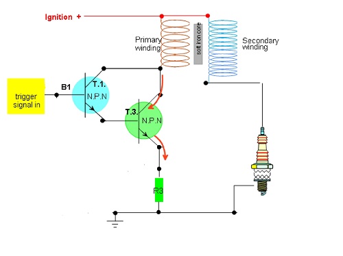 T1 NPN BC547 Collector current 100mA, HFE 110 to 800
 T3 the 2N3055 is a silicon Epitaxial-Base Planar NPN transistor mounted in Jedec TO-3 metal case.
It has a collector current of 15A which is large enough to switch the coil unlike T1. HFE 20 to 70
Ignition module
*function generator
Difficulties encountered in building this circuit:
The Resistor R3 reduced the current to a level that was too low for the spark plug to fire. It was removed and the circuit worked fine.
If I were going to build this circuit again what would I do differently?

References
No comments:
Post a Comment